03
Iterative Design and Aerodynamic Optimization of a Fixed-Wing UAV
A fixed-wing UAV designed for a 5 kg payload at 20 m/s cruise, taken from analytical sizing through OpenVSP and MATLAB optimization to ANSYS CFD validation.
- CFD
- Flight Mechanics
- Multidisciplinary Design
- Total weight
- ≈ 17.7 kg
- Power required
- ≈ 250 W
- Aspect ratio
- 10
Overview
- 5 kg payload, 20 m/s cruise, wingspan under 3 m
- Taught myself flight mechanics to complete the study
- Full workflow: concept → analytical model → CAD → CFD
Weight and performance estimation
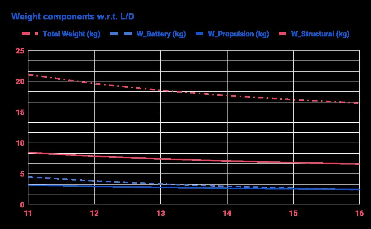
I started by estimating weight from the mission requirements, assuming structure at 40% and propulsion at 15% of total weight, with the battery sized from a 100 Wh/kg energy density and one-hour flight. A MATLAB script automated the aerodynamic calculations from the governing equations.
- Total weight ≈ 17.7 kg
- Power required ≈ 250 W
- Thrust required ≈ 12.4 N
Wing geometry and airfoil
The script plotted key parameters across the design space, which made the iterative selection much faster. Higher aspect ratio improves efficiency; lower improves maneuverability.
- Wing area 1.23 m², aspect ratio 10, CL 0.58, CD 0.042
- NACA 63-412 airfoil for high lift and stable cruise (design AoA 3°)
- NASA 64-012 tail, 0.35 m² tail area, CG at 0.18 m, 3° trim
CAD and CFD validation
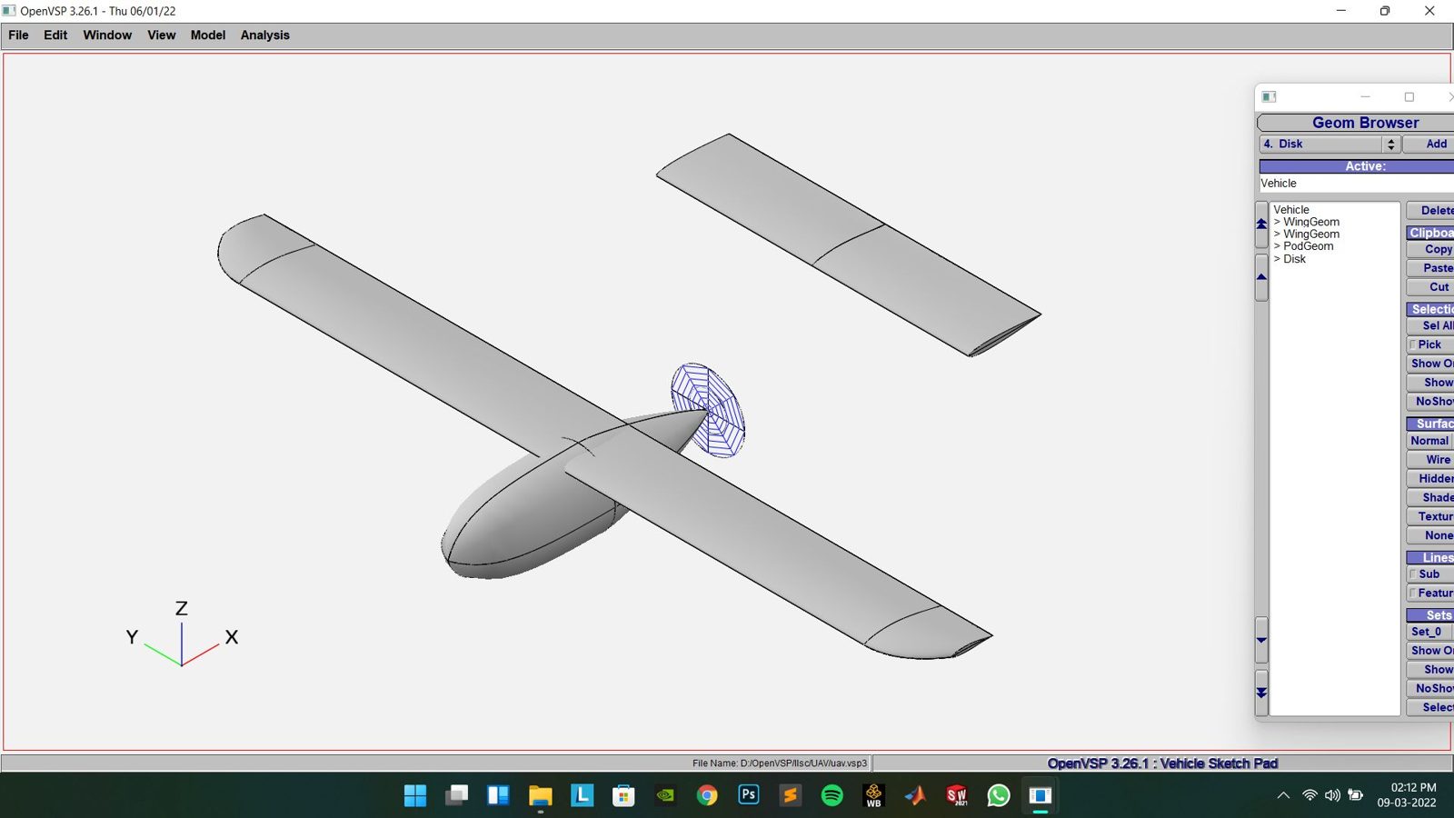
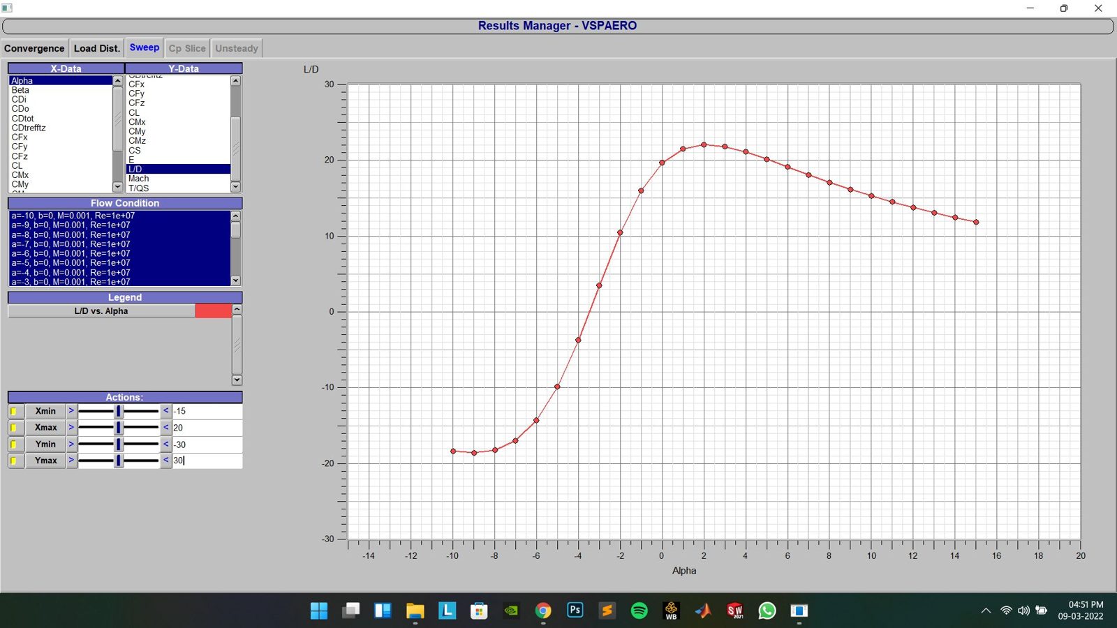
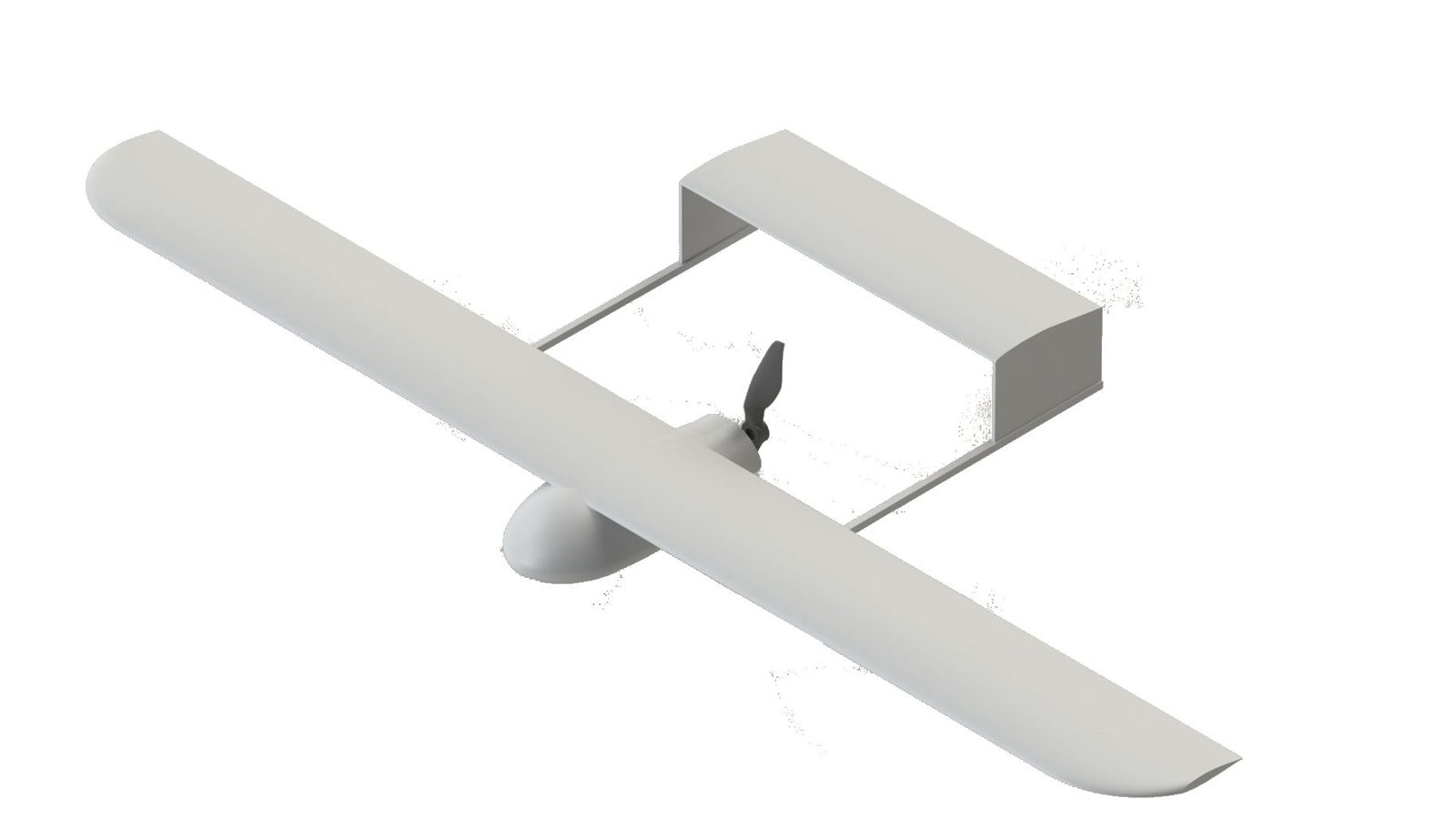
The UAV was modeled in OpenVSP and SolidWorks, then analyzed in ANSYS Fluent to check the aerodynamic coefficients against the OpenVSP and analytical predictions.
| Parameter | CFD | Analytical |
|---|---|---|
| CL (α = 0°) | 0.42 | 0.40 |
| CL (α = 3°) | 0.75 | 0.70 |
| CD (α = 3°) | 0.12 | 0.027 |