02
Design & Development of a Fully Faired Recumbent HPV
A fully faired recumbent human-powered vehicle for ASME HPVC 2020, developed over two iterations with a focus on ergonomics, handling, drivetrain efficiency, and aerodynamics.
- Composites
- Design Validation
- Material Selection
- Top speed
- 50 mph
- Drag coefficient
- 0.1
- Frontal area
- −60%
Overview
- Co-Captain; led design and manufacturing for the ASME HPVC 2020 vehicle
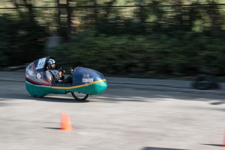
- Reached 50 mph on human power under competitive racing conditions
- Cut fairing manufacturing cost from ₹1.8L to ₹40K with in-house composites
Learning from previous vehicles
The team had built four vehicles before this one. When I took over design and manufacturing, we analyzed them and targeted their main weaknesses.
- Oversized fairings that added drag and weight
- Poor rider ergonomics and limited road visibility
- Low maneuverability
Ergonomics and power output
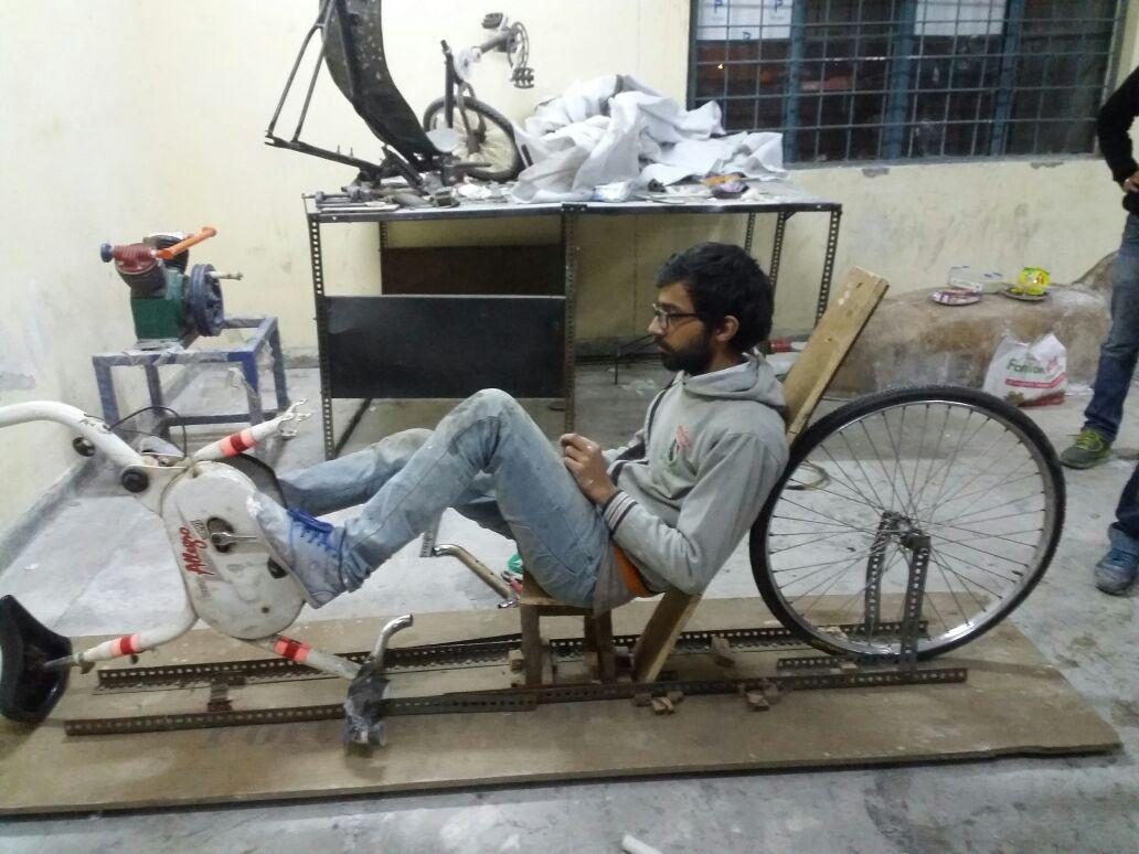
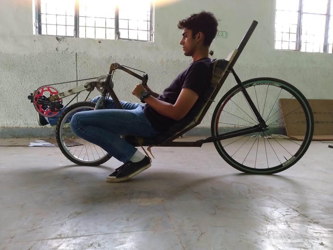
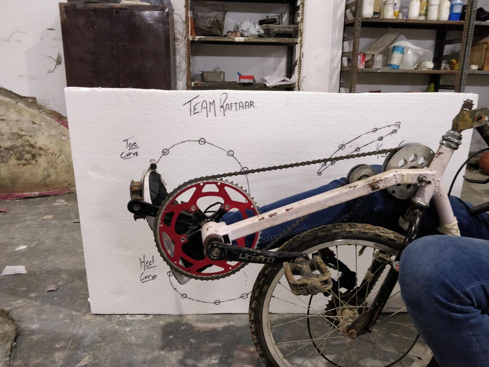
We built an adjustable seat rig to vary seat angle and position while collecting rider feedback. From the chosen position we located the crankshaft for efficient pedaling biomechanics and sufficient eye level, then checked turning capability against chainline and knee clearance.
Frame design and stability
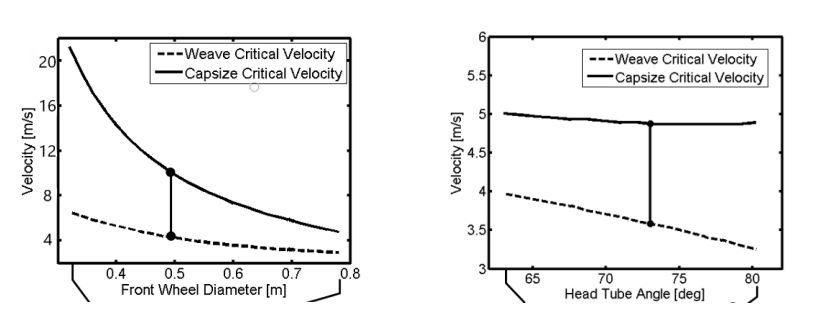
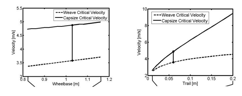
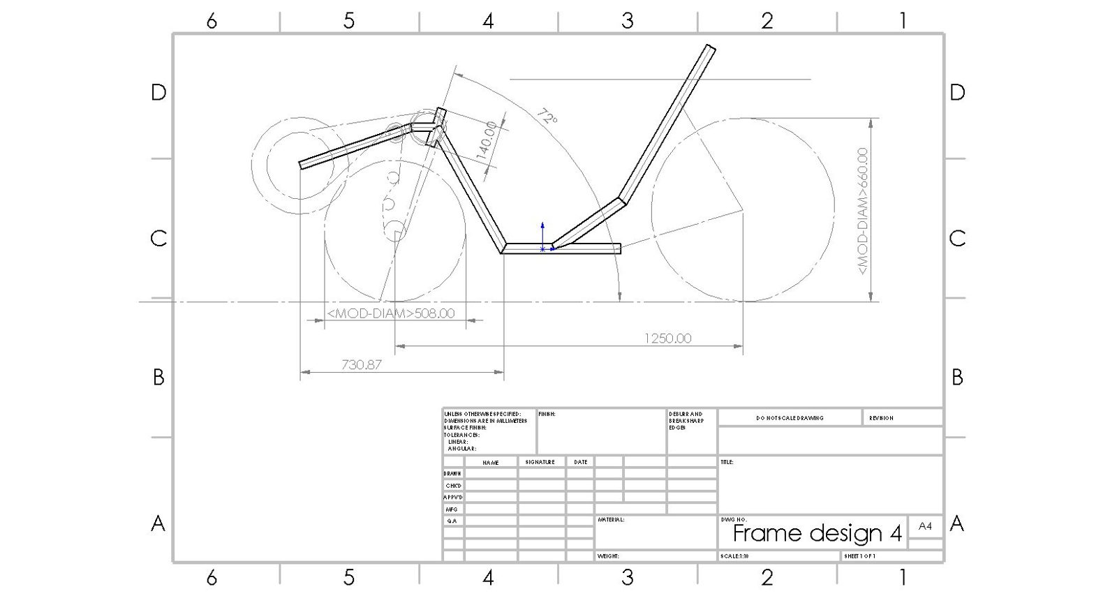
The frame uses AISI 4130 chromoly steel for its strength-to-weight balance. I ran a parameter study with the Whipple bicycle model, relating head tube angle, trail, wheelbase, and front wheel diameter to stability and high-speed performance.
Drivetrain and topology optimization
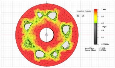
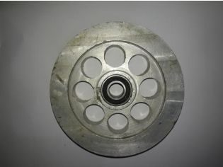
We measured real pedaling forces with a force-sensitive resistor and used them as load cases for topology optimization in Fusion 360. The resulting idler system routes the chain efficiently, relieves tension, and prevents derailment with minimal material.
A prototype frame was built and tested before the final frame went into production. I designed manufacturing fixtures for frame assembly, improving alignment accuracy and build repeatability.
Aerodynamic fairing
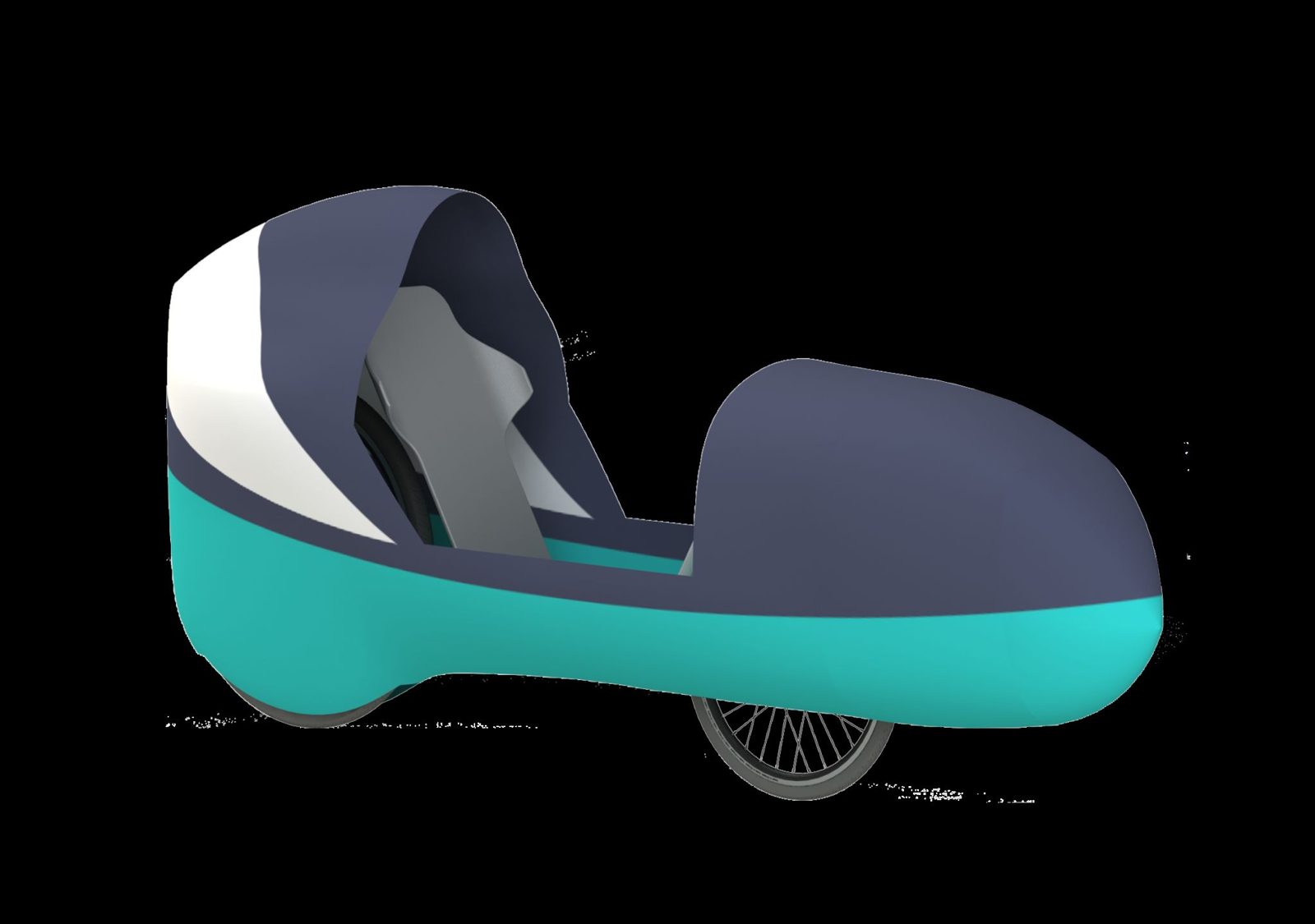
Fairing geometry was built around measured rider envelopes (shoulder width, heel and toe reach, knee curves) and iterated using airfoil sections, landing on a teardrop canopy that minimizes drag while keeping clearance.
CFD and structural validation
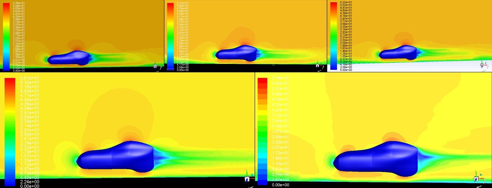
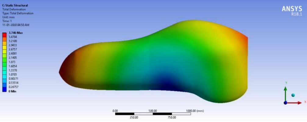
Steady-state RANS simulations used the k-omega turbulence model in ANSYS Fluent. The mesh was refined from ~350k to over 4 million elements, and the final independence study showed only 0.0018% variation. Top and side load tests confirmed the fairing's strength with high safety factors.
Composite manufacturing on a budget
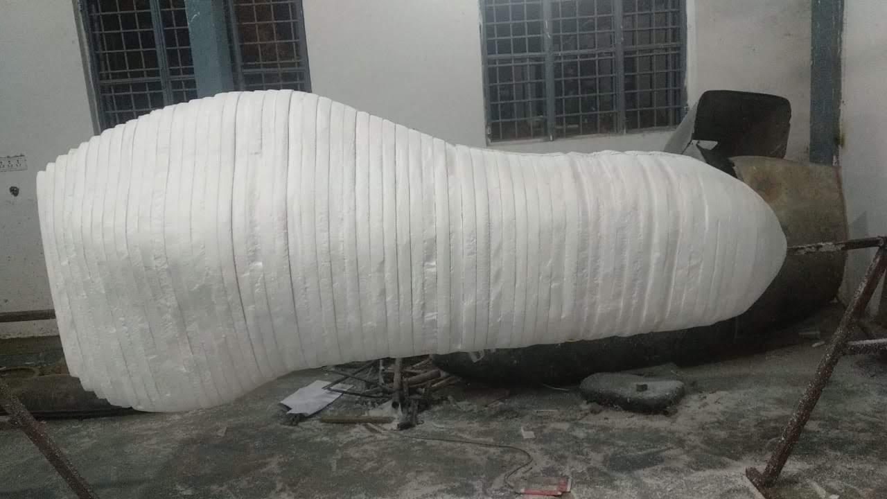
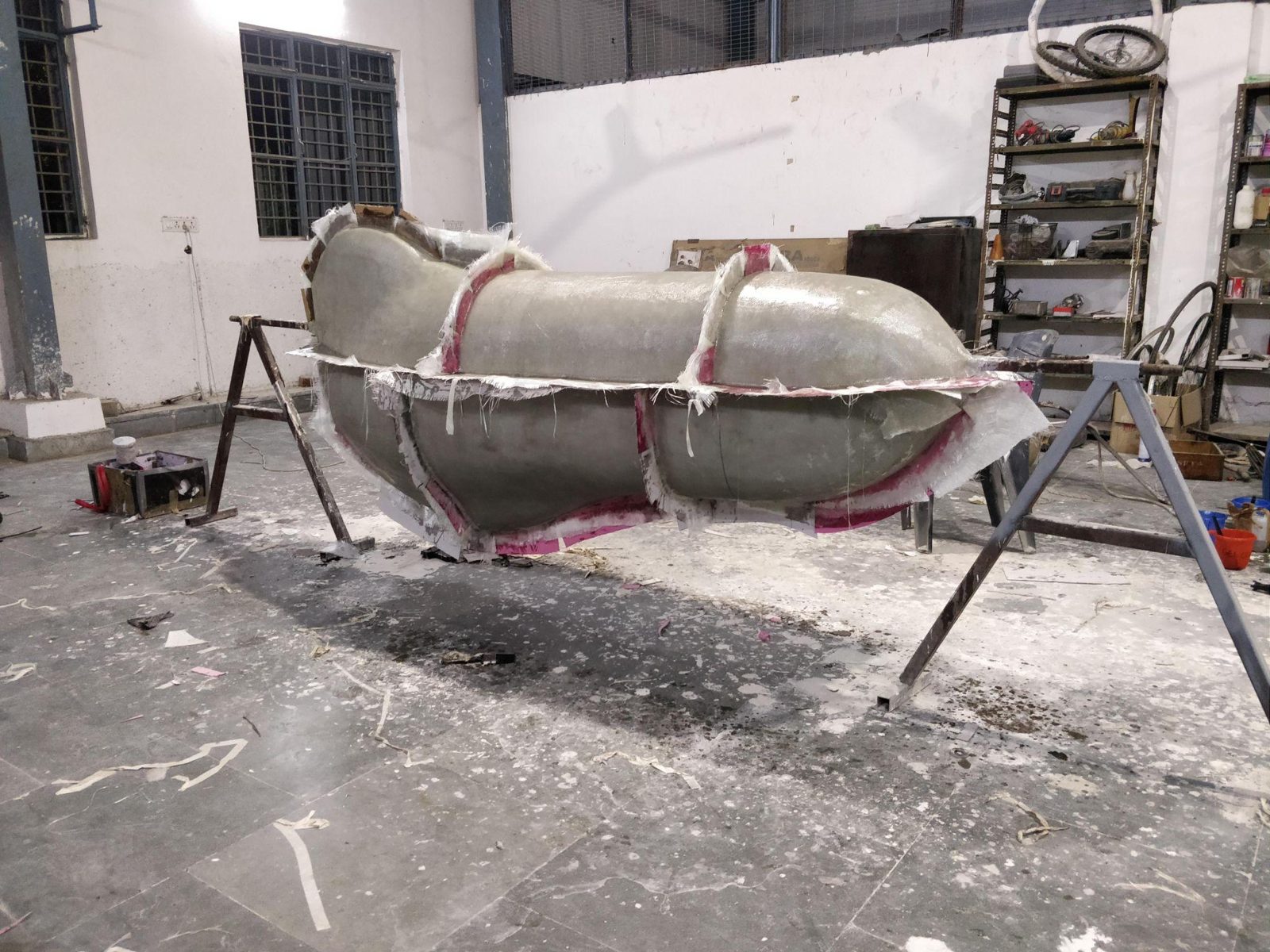
Fiberglass molds had been cheap but rough; CNC molds were excellent but too expensive. After testing four carbon fiber and Soric Lantor core layups, I developed a hybrid process: the fairing was split into 75 cross-sections cut from thermocol sheets, stacked, sanded, and coated with fiberglass and paint to form a pattern.
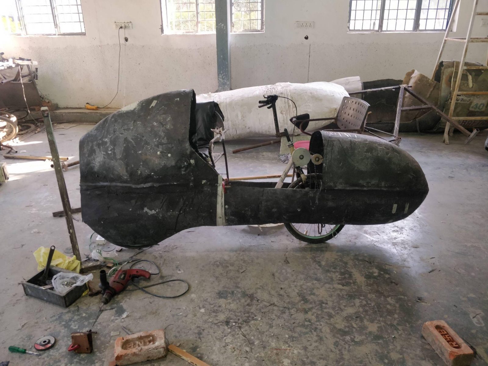
From that pattern we made 10 fiberglass molds and used them to lay up the final carbon fiber panels, which were then assembled into the fairing. The redesign and in-house process cut manufacturing cost from ₹1.8L to ₹40K, while reducing the drag coefficient to 0.1 and frontal area by about 60%.